ESP32 – Use built-in LED and BOOT Button
Did you know that the ESP32 has a built-in user LED and Utility Button? No need to build a simple circuit to do testing.
Overview
The ESP32 is an amazing Arduino device that has lots of GPIO pins, plenty of CPU and memory capacity, as well as built-in WiFi and Bluetooth, and many other features.
- The ESP32 has a built-in LED on pin 2, which you can use freely.
- You can use the BOOT button on GPIO0 as a utility button.
| Interface | Description |
|---|---|
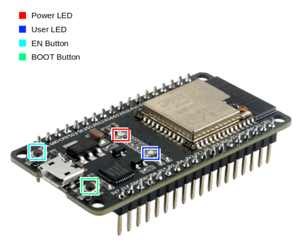
| ■ Power LED | Red when power is on |
| ■ User LED | Blue when activated by pulling GPIO2 HIGH. |
| ■ EN Button | “Enable”, normally HIGH. Pushing the button pulls LOW, which reboots. |
| ■ BOOT Button | When used with “EN”, causes the device to boot in to programming mode.
Normally GPIO0 is HIGH (Normal boot mode). Pushing the button pulls GPIO0 LOW (Enter programming / download mode). However, after the device boots normally, the BOOT button can be used to send input to GPIO0. |
Blink the Built-in LED
The LED is tied to GPIO2, or “pin 2”.
#define LED 2

void setup(){
  pinMode(LED, OUTPUT);    //set LED pin to output mode
  digitalWrite(LED, LOW);  //ensure LED is OFF
}

void loop(){
  digitalWrite(LED,HIGH);   //Turn LED ON
  delay(1000);              //Delay one second
  digitalWrite(LED,LOW);    //Turn LED OFF
  delay(1000);
}
In “setup()” we set the LED’s pin mode to output, meaning that the ESP32 will set the voltage value of the pin.
Since the ESP operates at 3.3 Volts (also known as “3v3”), setting the output pin “HIGH” sets the voltage level to 3.3 Volts. Setting the pin “LOW” sets the voltage level to 0 Volts.
In the loop, we turn the LED ON by setting the pin HIGH, wait a second, set the pin LOW, wait another second, then repeat forever.
For those unfamiliar with Arduino, setup() is executed after the device boots and after other inline code such as variable declarations. After setup() completes, loop() executes until the device is powered off.
Detect BOOT Button Press
The BOOT button is tied to GPIO0.
The ESP32 has two boot states,normal boot, and boot to programming (download) mode.
| Pin | No Boot / Reboot | Normal Boot | Programming Mode |
|---|---|---|---|
| EN | LOW | HIGH | HIGH |
| GPIO0 | – | HIGH | LOW |
| GPIO2 | – | LOW | NOT HIGH |
- Pushing the EN button pulls the EN pin low, causing the ESP32 to turn off, and releasing the button allows the device to boot.
- The BOOT button pulls GPIO0 HIGH (not pressed) or LOW (pressed). Holding BOOT and tapping EN will cause the ESP32 to enter programming mode.
However, after the device boots, the BOOT button can be used as a general-purpose input button by reading GPIO0!
In this example, when the BOOT button is pressed, ESP32 will give the user a message on the serial terminal and flash the LED:
#define BUTTON 0
#define LED 2

bool buttonState=LOW;     //global state variable

//--- Setup ---
void setup(){
  Serial.begin(9600);

  //* set LED pin to output mode
  pinMode(LED, OUTPUT);

  //* ensure LED is OFF
  digitalWrite(LED, LOW);

  //* Set GPIO0 to INPUT mode, pulled LOW
  pinMode(BUTTON, INPUT_PULLUP);

  //* Listen for interrupt on GPIO0
  attachInterrupt( digitalPinToInterrupt(BUTTON), buttonPress, FALLING );
}

//--- Interrupt handler ---
void buttonPress(){

  //* If button has NOT already been pushed...
  if (!buttonState){

    //* Set global state to HIGH (button has been pressed)
    buttonState = HIGH;

    //* Temporarily stop listening to GPIO0
    detachInterrupt( digitalPinToInterrupt(BUTTON) );
  }
}

//--- Main loop ---
void loop(){

  //* If interrupt has triggered...
  if(buttonState){

    //*** Begin button code / payload ***

    //* Send user message to serial terminal
    Serial.println("\nBUTTON PRESS!!!");

    //* Flash the built-in LED
    digitalWrite(LED,HIGH);  //* Turn LED ON
    delay(1000);             //* Delay one second
    digitalWrite(LED,LOW);   //* Turn LED OFF

    //*** End button code / payload ***

    //* Reset global state to LOW
    buttonState=LOW;

    //* Start listening again to GPIO0
    attachInterrupt( digitalPinToInterrupt(BUTTON), buttonPress, FALLING );
  }

  //* Delay 100ms
  delay(100);
}
Here is the program flow:
- Define LED and BUTTON pins (GPIO2 and GPIO0, respectively)
- Declare global variable to track whether an interrupt has been triggered (buttonState)
- In setup:
- Connect to serial terminal
- Set the LED (GPIO2) pin to OUTPUT and set to LOW (off)
- Set the BUTTON (GPIO0) pin to INPUT, pulled HIGH (normal operating state)
- Attach an interrupt to GPIO0, triggered when the pin changes from HIGH to LOW (FALLING). This also defines the interrupt handler, buttonPress().
- When the user presses the BOOT button, GPIO0 changes state from HIGH to LOW, triggering the interrupt, which calls the buttonPress() function.
- Interrupt handlers should be extremely lightweight. Here, we set a flag (buttonState) to indicate that the button was pressed, and let the main loop do the heavy lifting
- The last thing the handler does is to “detach” (or stop listening) from GPIO0. This prevents subsequent interrupts from firing until the main loop processes the initial interrupt.
- In the main loop, we look for “buttonState” to be true (HIGH). This is a global variable to indicate that a “button press” event has occurred, and has nothing to do with the actual voltage level on GPIO0.
- The first thing we process is the “payload”, or whatever code we want to run when the user presses a button. In this case, we give the user a message on the terminal, and blink the built-in LED.
- After we finish processing the payload, we reset the global state variable (buttonState) to LOW, so that we are ready for the next interrupt.
- The last step is to re-enable the interrupt listener on GPIO0.
- You should ALWAYS have a small delay in the main loop. This prevents the CPU from entering what’s called a race condition, where the CPU is operating at full power because it’s constantly processing code, executing an infinite loop. A delay of even a few milliseconds allows the CPU to rest, which reduces power consumption as well as heat generated by the CPU. You can actually test this by removing the final “delay” statement, and feeling that the CPU starts to get warm after a few seconds after initial boot. Normally I would use delay(10), or 10 milliseconds, which allows the device to be super-responsive to user input. However, in this example, 100ms per loop is more than sufficient.
In Summary
- Pushing the BOOT button pulls GPIO0 LOW
- When GPIO0 changes state from HIGH to LOW, this triggers an interrupt
- The CPU handles the interrupt by calling the interrupt handler function, “buttonPress”
- The job of buttonPress is to be as lightweight and fast as possible. buttonPress sets a global flag, “buttonState”, disables the interrupt, and exits.
- We disable the interrupt to prevent what’s called “re-entrance”, which means multiple events can enter the handler code at different times, which could be unstable and unpredictable.
- During the next iteration of the main loop, it looks at the “buttonState” flag to determine whether to execute the button payload
- In this example, the button payload gives the user a message, then resets the global flag to false (LOW), and re-enables the interrupt.
- Whether the payload has executed or not, when the user releases the BOOT button, GPIO0 changes state from LOW to HIGH (normal state), which does NOT trigger the interrupt because the interrupt is looking for HIGH -> LOW transition.
Thank you for reading, and I hope you found this helpful!