I’ve always wanted to write my own tetris clone. I wrote one in javascript. To give it a retro feel, I implemented the game using text graphics.
Math and Science
Science is a tool that mankind uses to expand our technical knowledge of the world and universe around us.
People use the term “science” broadly, but it has a specific meaning:
Performing an experiment to determine the outcome of a closed system when an independent variable within that system is modified.
You don’t have to have a degree to be a scientist. A scientist is anyone who follows a rigorous scientific process, called the scientific method:
Observe, Analyze, Hypothesize, Experiment, Conclude, Repeat
Please enjoy these science-related posts.
We all know (well, HOPEFULLY we ALL know) that investing in cryptocurrency is fraught with risk. However, with the promise of privacy and decentralized banking, doesn’t crypto do more good than bad?
In short, NO. Keep reading to find out why…
Unfortunately, these two things have absolutely no relationship to each other.
Recently, while working on a sheet metal project, I was annoyed that I had to go find a sheet metal gauge chart, because sheet metal is pretty much only sold in “gauge” thickness. I was even more annoyed to find that different metals have different gauges. So 14 gauge stainless is not the same as 14 gauge copper, and neither of these are the same as 14 gauge aluminum
Bore Gauge
Although this is an outdated system, its only modern vestige applies to shotguns.
And it goes like this:
The bore gauge number (n) is the diameter of the bore, such that n lead balls of equal diameter weigh 1 pound.
Therefore, the greater the bore gauge, the smaller the diameter.
So when is 12 > 20? When you’re talking about bore gauge.
Yep. That’s bad. But, it’s at least manageably bad. There is at least a formula.
Lead weighs about 11.8 ounces of weight per ounce of volume.
A pound of lead (16 weight ounces) would therefore occupy a mere 16 / 11.8 = 1.35 fluid ounces.
To relate volume and diameter, we have to convert fluid ounces to inches, and 1 ounce of volume = 1.8 cubic inches.
Therefore, 1.35 fluid ounces of lead = 1.35 * 1.8 = 2.43 cubic inches.
At this point we have 2.43 cubic inches of lead, which we know is enough for a “1 gauge” lead ball, but we need to find the diameter.
Volume of a sphere (V) = 4 / 3 * Pi * r^3
r = Radius
r^3 = Radius to the 3rd power (cubed)
Since we have the volume and we need the diameter, we need to rearrange this to solve for radius, then multiply by 2 (diameter = 2 * radius)
d = 2 * ( (3 * V) / (4 * Pi)) ^ 0.3333
By inverting ^3 (cubed) as ^ 0.3333 we get the cubed root
If we compute this for our 2.43 cubic inches of lead, we get:
d = 2 * ( (3 * 2.43) / (4 * Pi)) ^ 0.3333
d = 2 * ( 7.29 / 12.57 ) ^ 0.3333
d = 2 * 0.58 ^ 0.3333
d = 2 * 0.83
d = 1.667 inches
A 1 gauge bore diameter is 1.667 inches.
For the general case, we can start by computing the amount of lead. Since volume and weight are proportional, and the volume of a pound of lead is constant:
V = 2.43 / g
2.43 = 1 pound of lead in cubic inches
g = gauge number
We then take the same formula, substitute for V, and pre-compute some constants:
d = 2 * ( ( 3 * 2.43 / g ) / (4 * Pi )) ^ 0.3333
d = 2 * ( 0.58 / g ) ^ 0.3333
We can cube both sides and further simplify:
d ^ 3 = 8 * 0.58 / g
d ^ 3 = 4.64 / g
d = 1.668 / g ^ 0.3333
And, we can use this for any gauge number (g):
| Gauge | Diameter |
| 10 | d = 1.668 / 10 ^ 0.3333
d = 1.668 / 2.154 d = 0.77 inches |
| 12 | d = 1.668 / 12 ^ 0.3333
d = 1.668 / 2.289 d = 0.73 inches |
| 20 | d = 1.668 / 20 ^ 0.3333
d = 1.668 / 2.714 d = 0.61 inches |
And, you can plug any number in to this formula, so if you wanted a 14.5 gauge bore size (for whatever reason), you would use the same formula above, and that bore size is 0.68 inches.
You can even reverse the process to find the bore gauge corresponding to a given diameter measured in inches, by solving for gauge:
d = 1.668 / g ^ 0.3333
d ^ 3 = 4.64 / g
g = 4.64 / d ^ 3
A .357 magnum has a nominal bore diameter of 0.354 inches. If we plug in 0.354, we get:
g = 4.64 / 0.354 ^ 3
g = 4.64 / 0.0444
g = 104.6
So the next time you threaten someone, you can say “Don’t make me pull out my 104 gauge!”, and at least this has an obscure but discernible meaning.
How did we get stuck with this standard? Nobody really knows! However, most texts state that gauge was used even as late as 200 years ago, when there weren’t any good, universal measuring standards. If you ordered ammunition in gauge size, you were assured that it would match your gun’s bore diameter. As the rifle (gun with a rifled barrel) is a relatively new invention, measurements were much more standardized by that time, and it makes sense that rifle bore sizes (caliber) are always measured in inches or millimeters.
However, to this day, most shotguns are still smooth-bore, because shotgun cartridges have multiple, small projectiles (called pellets) that spray out in a disc formation when the cartridge is fired. Because the pellets are much smaller than the shotgun’s bore, they don’t come in to contact with the barrel enough for rifling to be effective. Although there are rifled shotguns (called slug guns) that are designed for shooting a single, solid lead shot (called a slug), these are uncommon. Therefore, it makes sense that we’ve kept the tradition of measuring a shotgun’s smooth bore size in gauge, rather than using caliber.
Fortunately, today, bore gauge is only used for shotguns, and rifle bores have become so standardized that I can go anywhere in the world and purchase ammunition for a gun of the same caliber manufactured anywhere else in the world.
Now, let’s talk about sheet metal gauge.
Sheet Metal Gauge
Here is the formula for sheet metal gauge:
There isn’t one. Consult a gauge chart.
But, it gets even better.
Sheet metal gauge is based on density, so not only do you need a gauge chart, you need a different gauge chart for each type of sheet metal.
How did we end up with this?
Sheet metal gauge size is based on wire gauge size, but not AWG, which is the American standard for wire gauge size.
Back in the early days, each vendor had their own wire gauge size, based on the number of machining steps required in order to get down to that gauge size. E.g. 10 gauge wire requires 10 steps. Eventually, all of that got standardized as the American Wire Gauge (AWG) standard.
Wire has been mass-produced much longer than sheet metal, so when sheet metal started to be mass-produced, the sheet metal manufacturers adopted the wire gauge standard (but not AWG), and each manufacturer had their own.
Over time, like AWG, sheet metal gauge sizes became standardized.
Unlike AWG which specifies a standard wire diameter independent of any other factor (e.g. 20 gauge wire is the same diameter in copper or aluminum, or steel, or whatever), sheet metal gauge is based on density, so the gauge size changes based on the specified material.
Nominally, every reference to sheet metal states that gauge size is based on “a density of 41.82 pounds per square foot”, but that’s not the case. If it was the case, you would be able to work backwards to find the gauge number. For example, going back to the way bore gauge works, if 41.82 pounds = 1 (sheet metal) gauge, then dividing that by 2 = 2 gauge, etc. But that’s not the case. 10 gauge (steel) = 0.1345 inches, and if we multiply that by 10, we get 1.35 inches. 20 gauge = 0.0359 inches, and if we multiply that by 20, we only get 0.72 inches. So there is clearly no proportionality based on weight or thickness.
If you google for a sheet metal gauge formula, you can find plenty of references that all begin with:
Sheet metal gauge size is based on 41.82 pounds per square foot. Consult your sheet metal gauge chart, and…
As it turns out, this is a formula for calculating the weight based on gauge size, not for calculating gauge size.
Why do we still use this archaic standard? Sheet metal gauge is codified by U.S. law, for tax purposes: 15 USC 206: Standard gauge for sheet and plate iron and steel.
So, because the government regulates the thickness of sheet metal for tax purposes, you have to consult a gauge chart whenever you order sheet metal.
This morning, July 20, 2021, Blue Origin’s New Shepard rocket launched in to space for its first 11-minute passenger flight.
Congrats to Bezos and team!
HOWEVER, the commentator on one of the science channels made this statement: “The rocket needs to go high enough to reach orbit, even briefly”
A popular misconception is that orbit and outer space are the same thing – actually, I’ve written about this previously. However, I would expect a science commentator on a science-related channel to know the difference!
Just to recap:
- The Kármán Line, at 100Km (about 62 miles) above the Earth’s surface is considered for treaty purposes to be the delineator between the Earth and “outer space”. From what I can tell, New Shepard will briefly surpass this, making all of its passengers “official” astronauts.
- For reference, the International Space Station’s orbit fluctuates, but the average is about 240 miles above Earth’s surface.
- Reaching outer space doesn’t automatically mean that you are in orbit, nor that you somehow magically become weightless.
Even hundreds of thousands of miles away from the surface, any object is still within the Earth’s gravitational influence. So, if you fire a rocket straight up (perpendicular to the Earth’s surface), even hundreds or even thousands of miles in to space, eventually, the rocket will run out of fuel, and the Earth’s gravity will pull it back down.
In orbit, however, an object’s velocity parallel to the Earth’s surface creates centrifugal force which balances the pull gravity.

E. A rocket launched perpendicular to the Earth’s surface eventually runs out of fuel and is pulled back down by gravity. F. To achieve orbit, a rocket must attain both height and velocity parallel to the surface.
My understanding of New Shepard is that it will basically travel straight up, give the passengers a few minutes of weightlessness, and then return to Earth.
Although gravity will be acting on the spaceship and its passengers during the descent, the passengers will experience weightlessness (which is different than outer space and also different than orbit) because gravity acts on both nearly-equally. The state or sensation of weightlessness occurs when there are no net forces acting on the passengers, which is only true inside the ship, and only relative to the ship itself.
Although the exact height of the New Shepard’s mission isn’t listed, it is expected to go “well above” the Kármán Line. So if we were to guess 65 miles, we would be in the right ball park.
This means that New Shepard’s velocity at 65 miles above the Earth’s surface will be zero, after its rockets turn off, and gravity bleeds away all of its upward velocity. At that exact point, with gravity acting constantly, it will begin to accelerate back down to Earth. Until the ship hits turbulence in the atmosphere, or they fire their re-entry rocket, the passengers will continue to fall at an ever faster rate toward Earth, pulled by gravity, yet experiencing weightlessness within the ship.
In contrast, to attain orbit at 65 miles above the Earth’s surface, the ship would have to be travelling almost 17,780 miles per hour parallel to the Earth’s surface in order to have enough centrifugal force to exactly counter the force of gravity.
How do we go about calculating this? Glad you asked…
Force of gravity:
F = m ⋅ g
- m = mass of the object
- g = acceleration due to gravity
Centrifugal force (same as centripetal force, but in the opposite direction):
F = m ⋅ v2 r
- m = mass of the object
- v = linear velocity
- r = radius of the orbit (from the center of the Earth)
In orbit, the net force is zero, so:
m ⋅ g = m ⋅ v2 r We quickly see that mass is irrelevant, and we can solve for v:
v = √ g ⋅ r
If we measure gravity and orbital radius in feet, we get orbital velocity in feet per second. To simplify things, we can use 78,545 miles per hour2 as the acceleration due to gravity:
v = √ 78545 ⋅ r
The radius of the Earth is about 3960 miles. To find orbital velocity, we have to have the radius from the center of the Earth, which include’s the Earth’s radius plus the height above the surface:
v = √ 78545 ⋅ ( 3960 + r )
If we plug in 65 miles, we get about 17,780 miles per hour required for orbit.
So again, good luck to Bezos and team – although you won’t be “in orbit”, you will definitely be in outer space.
Find the Center of a Circle Using Only a Pencil and Straight Edge
I bought a wood lathe recently, and the first time I tried to center some wood, I went through the painful process of remembering how to find the center of a circle. This, despite having had three years of mechanical drawing classes.

Starting with a pencil and straight edge:
- Mark a line on the straight edge that’s a little more than 3/4 of the diameter (height) of the circle. It doesn’t have to be exact.
- Make a mark (M) at the top of the circle. The location of the mark need not be exact.
- Align the straight edge so that the corner is on mark M, and the line on the straight edge touches the right edge of the circle. Draw a line (A) from somewhere above the center of the circle out to it’s edge.
- Repeat on the left side, drawing line B.
- From where line B ends, line up the straight edge so that its corner sits on the end of line B, and its line touches the lower-right-hand edge of the circle. Draw line C along the straight edge, crossing the vertical center line.
- Repeat from the end of line A to the lower-left-hand edge of the circle, and draw line D
- At this point, lines C and D should form an “X” near the bottom of the circle.
- Draw a vertical center line (E) by aligning the straight edge with mark M and the intersection of lines C and D. Start the line above the center, and go all the way to the bottom edge.
- At this point, line E passes through the center vertically, but we need to find the horizontal center.
- From where line E touches the bottom of the circle, align the straight edge so that it crosses line A, and the line on the straight edge touches the upper-right-hand edge of the circle. Draw line F, crossing line A.
- Repeat this on the left side, crossing line B, and drawing line G.
- At this point, there should be an “X” on the left formed by lines B and G, and one on the right formed by lines A and F.
- Align the straight edge across the intersections of the left (B,G) and right (A,F) intersections, and draw the horizontal center line H.
The center of the circle is at the intersection of the vertical (E) and horizontal (H) center lines.
How This Works
Let’s call the distance from the corner of the straight edge to its mark S.
Let’s call the points where the horizontal center line meets the circle’s edges H1 (left) and H2 (right), and the point where the vertical center line meets the bottom V.
If we start at M and walk clockwise around the circle, we would pass through the points as follows: M (start) → H2 → V → H1 → M (back to start).

If the radius is 1, then the diameter is 2, and the length of MH2 is 1.41. We initially selected S to be about 3/4 of the diameter, or about 1.5.
The circle’s radius, R, is 1/2 the length of MV or H1H2. The length of MH2 would be √ R2 + R2 , and the same is true for H2V, VH1, and H1M.
If we assume that the radius R is “1 unit” (the actual length is irrelevant), then √ 12 + 12 = √ 2 , or about 1.41.
If the radius R = “1 unit” then the diameter = 2 ⋅ R = “2 units”.
By selecting S such that S is 3/4 of the diameter, 3/4 ⋅ 2 = 1.5. Since S>1.41, and we make two consecutive S-length marks around the circle, we know for a fact that 2 ⋅ S is greater than the length of MH2V.
By doing this twice, once clockwise, and once counterclockwise, we get lines C and D. We can call their intersection point T
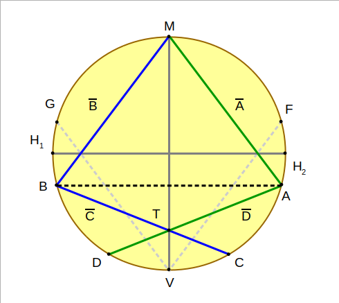
MAD = MBC = 2⋅S. Point T is located at the intersection of lines C and D. Triangles ΔMAT and ΔMBT are congruent. MT bisects AB.
⋅
It’s easy to prove that this forms two congruent triangles: ΔMAT and ΔMBT. If the line MT is the base of both, then because they are congruent, the height of both are the same, which means that MT perfectly bisects AB).
Since this line MT also bisects the equilateral triangle ΔMAB which is inscribed within the circle, that line must pass through the center of the circle as well.
Carrying MT out to the edge of the circle gives us point V.
By drawing a line from V of length S to the edge, we get line F, which crosses line A. We can call this intersection point U.

Points U and W are at the intersections of A and F, and B and G respectively. MUV is equilateral because MU=UV. MUV is congruent to MWV.
If we knew where the center of the circle (point O) was located, we could make the congruent triangle argument, that ΔMUO is congruent to ΔVUO, and just as with the vertical center line bisecting ΔMAB, UO would perfectly bisect the larger equilateral triangle ΔMUV.
On the other side, we draw line G of length S, which crosses line B at point W. Same congruency argument: ΔMWO is congruent to ΔVWO, and WO bisects equilateral triangle ΔMWV.
Because MU = VU we know that ΔMUV is equilateral, and the same for ΔMWV. Further, because of the congruency argument, we know that MU = MW and VU = VW, and therefore ΔMUV is congruent to ΔMWV.
If line UO bisects triangle ΔMUV, then it must intersect MV exactly at its center. Same for WO and triangle ΔMWV.
Therefore, WU passes through the center of both triangles at point O, where WU intersects MV.
And therefore, point O must be at the center of the circle, because VO = MO, and we know that MV passes through the center of the circle.
Note that this trick ONLY works if the the mark on the ruler (distance S) is > 1.41 times the radius.
If you have a set of things, a permutation is a specific way that you can list those things. Although algorithms exist to list every permutation, most of them rely on recursion – the calling of a function from within itself – which is horribly inefficient.
If you want a non-recursive algorithm that lists every permutation, keep reading…
SIMulation vs EMulation
This question came up in the context of another topic, and I immediately envisioned an excellent interview question:
Explain the difference between simulation and emulation
As someone who has written thousands of simulations, this is how I would answer that question…
SIMulation
Simulation is a closed system where the state “S” contains all relevant variables and their values, and S(i) describes those values at a specific iteration within the simulation.
S = { V0..Vk }
S(i) = {V0,i; V1,i; .. Vk,i}
Based on the variable values in S(i) and a system of rules A{R0… Rm}, the simulation calculates a new state, S(i+1).
In the simulation, we have a starting state, S(0) and an eventual end-state S(n), which is created after n iterations of the simulation. We start with S(0) and apply the rules of A{} in order to obtain S(1), and this continues until we reach S(n).
So explicitly, a simulation requires feedback from the current state in order to create a subsequent state, given a specific set of variable values and a specific set of rules that operate on those values.
EMulation
Emulation is a simulation whose rules are copied from another system.
Given a set of rules that describe system B: {R0..Rm}, if system A is an emulation of B then it simply contains the same rules:
A = B = {R0..Rm}
Given any state S(i) and a set of rules A{}, if we apply those rules to the current state, we get a new state S(i+1):
S(i+1) = A{} -> S(i)
Given the same state S(i) and another set of rules B{}, if we apply the rules in B{} to the current state S(i), we get S'(i+1), which is an “alternate-reality copy” of S(i+1):
S'(i+1) = B{} -> S(i)
If two different sets of rules A{} and B{} applied to any possible state S(i) produce the same next state, then:
S'(i+1) = S(i+1)
And therefore:
A is an emulation of B or vice-versa.
The important detail is that both systems A and B are equivalent, but they might not be implemented the same way – for example, the rules of B might be implemented in hardware, while A might be a software emulation of B.
Comparison
Emulation is a specific simulation that answers the question: “how would some other specific system respond, given a state of S”.
Conversely, in a simulation, you can have a set of independent rules that aren’t tied to any other system – the simulation is simply answering the question: “what would happen, if…”
I’ve seen definitions of both simulation and emulation that tie to copying something from the real world, but I disagree. For example, I could easily write a simulation of a 4D solid traversing 3D space, which is a completely hypothetical model that has no tie to the real world.
Likewise, if you copy the rules of some arbitrary simulation over to another system, then you’ve emulated the original simulation, with no ties to the real world – for example, you could emulate our clearly-contrived 4D solid simulation by copying its rules from a state diagram or a set of software commands to some other equivalent logical system – for example, the logical rules within a game simulation.
Which brings us to a final point: Simulations (and by extension, emulations) can contain other simulations. For example, you could have a simulation of a digital pet within a simulation of a digital world. The state logic and iteration of the digital pet could be driven inside the world simulation, or it could be driven externally and simply rendered based on its current state. If the digital pet is driven inside the world simulation, it could be driven within the code of the simulation (created at compile time), or it could be implemented as part of the logical rules of the world – for example, as a script or state machine that’s created using in-world tools during runtime.
Why the Sun does NOT track East-West
(Most of the time)
We were brought up learning “the sun rises in the east, and sets in the west”, which is absolutely true.
Anyone with experience in the outdoors, including scouting, will probably have been told:
In the morning, follow your shadow to travel west.
In the afternoon, follow your shadow to travel east.
And… moss grows on the north sides of trees, etc…
HOWEVER….
That’s not always EXACTLY true…
About a year ago, I had a discussion about a road that runs north-south, and why the sun doesn’t track east-west.
It went like this:
Him: East is THAT way (points southwest)
Me: Um… No. The road there runs north-south, so east is perpendicular to that road.
Him: Well, I was always taught that the sun points east-west.
Me: That’s not exactly true, because the Earth is tilted on its access, causing certain parts of the Earth’s surface to be closer to the sun…
Him: I don’t believe all that…
Me: It’s spring. Go stand at the fence pole and walk from the fence to the house, following the sun’s path. Then, do it again, same time of day, 6 months from now.
(To this day, we disagree on due east)
When I instinctively mentioned the Earth’s orbit, and the 23 degree tilt of Earth’s axis, I knew that to be correct, but I ended up dwelling on the actual mechanics.
So, here we go…
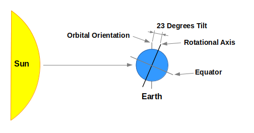
The Earth is tilted on its rotational axis by 23 degrees, relative to its orbital orientation around the sun.
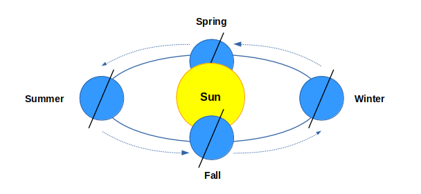
As a result, over the course of a year, which is the Earth’s orbital period, that tilt causes the Earth’s orientation relative to its orbital plane to change.
In the winter and summer, if you were to slice through the center of the sun with a big knife, along the axis of the Earth’s rotation, the sun would be sliced vertically – perpendicular to the orbital plane, which is the path that the Earth follows as it orbits the sun.
However, in the spring and fall (and all other times), the Earth is canted with respect to the orbital plane, and thus if you were to slice through the sun’s center with a knife aligned with the Earth’s rotational axis, the sun would be cut at an angle with respect to the orbital plane.
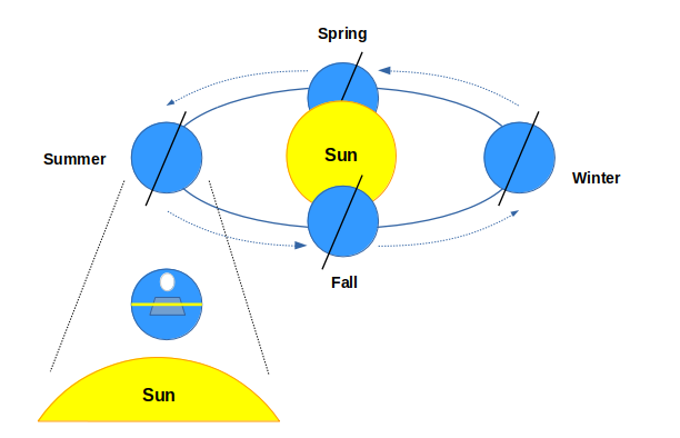
In the summer, the Earth’s north pole is canted toward the sun. From the sun’s perspective, its track is perfectly parallel to the Earth’s equator, which is perpendicular to the Earth’s rotational axis.
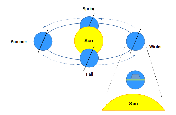
Likewise, in the winter, although the Earth’s north pole is canted away from the sun, the sun’s track is still parallel to the Earth’s equator.

In the spring and fall, the plane of the Earth’s rotational axis is tilted from the sun’s perspective.
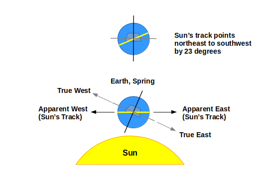
In the spring, from the sun’s perspective, the Earth appears tilted to the right, causing the sun’s track to pass along a path that’s rotated counter-clockwise relative to the Earth’s equator and rotational axis.

Likewise, in the fall, the Earth is tilted in the opposite direction due to its orbit, and the sun’s track appears rotated clockwise relative to the Earth’s equator and rotational axis.
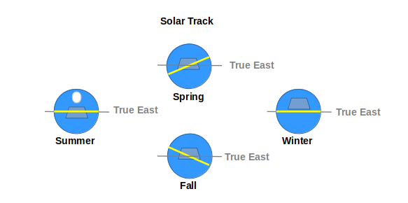
Thus, in winter or summer, the sun’s track follows a true east-west path. At every other time, the Earth appears slightly tilted to the sun, causing the sun’s track to follow a northeast-southwest path in the spring, or a southwest-northeast path in the fall.
So, to all of you scouts out there…
- In the winter or summer, your shadow points east-west.
- In the fall, put the sun over your right shoulder to follow an east-west path.
- Likewise, in the spring, put the sun over your left shoulder to follow an east-west path
- When a map shows that a road runs north-south or east-west, it runs north-south or east-west, regardless of where the sun points.
Or, why floating point operations are slow, and how to avoid them.
Using a color scale to visualize output makes it easy to understand data, and see patterns that aren’t intuitive.
A simple 1 or 2-color scale is really simple to implement, but what if you want to use the whole spectrum?