[Updated 2022-08-03 – Master Cable Break-Out]
- [Update to the Update, 2022-08-07 – Dead Control Board]
[Updated 2019-06-12 – Additional Pictures and To-Do]
[Original 2019-06-09]
We just completed a big move from east of Dallas to south of Fort Worth. This is a big move for us, not just in terms of distance (about 70 miles), but in terms of house and property as well. The old house was a 1,900 sq ft 3-bedroom on a tiny lot, around 1/4 acre, and the new house is just over 5,000 sq ft, 5 bedrooms, on about 1.5 acres.
The front fence is about 300 feet from the house, and there is a big, steel gate at the front, operated by a Mighty Mule gate opener.
The gate controller uses coded remotes that have a very short range – only about 20 feet with a clear line of sight, which is not very convenient.
Which brings us to…
Justin’s Adventures with the Gate Controller
Table of Contents
Typical Installation
In a typical installation, there is a swinging gate, where the electrically-operated gate actuator attaches.
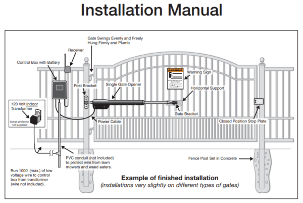
The gate control box, located a short distance from the actuator, houses the gate controller board, and connects to the receiver antenna.
The whole system runs on a 12V battery located inside the control box, that is continuously charged by the controller board. Input voltage is from an 18V DC charger connected to 120V AC line voltage.
When you press the transmitter button, the receiver sends a signal to the controller board, which then cycles (opens or closes) the gate.
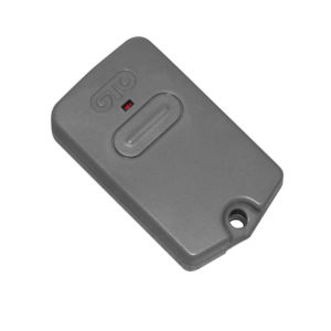
FM135 Keychain Clicker
The transmitter can be programmed with one of 3^9 codes using a series of dip switches located inside the remote. Obviously, the first thing I did was to reprogram the remote so that it no longer uses the factory default code. :-/
In our case, there are some additional accessories installed.
FM136 Wireless Intercom and Keypad

You put the keypad on a post, and can be programmed with up to 25 codes to allow entry without a transmitter. Inside the keypad are the same 9 dip switches, and you set the same code that your transmitter uses. When the correct key code is entered, it transmits a signal to the receiver (sitting a short distance away), which then cycles the gate.
This is a convenient feature for friends and relatives who don’t have a transmitter, and it even supports temporary codes – for example, if you are expecting a delivery, you can program a code that only works for 1 day, and automatically expires. If you have guests over for the weekend, you can give them a personal code that expires after 3 days, etc…
The other part of this accessory is the intercom system.
From the keypad, you can “call” the base station, and conduct a voice conversation, similar to a wireless intercom. From the base station, pressing a button cycles the gate, or you can “hang up” by pressing the “End Call” button.
In our case, the distance to the house far exceeds the range of the base station, so although the keypad is quite handy, the base station is completely useless.
FM138 Driveway Exit Wand
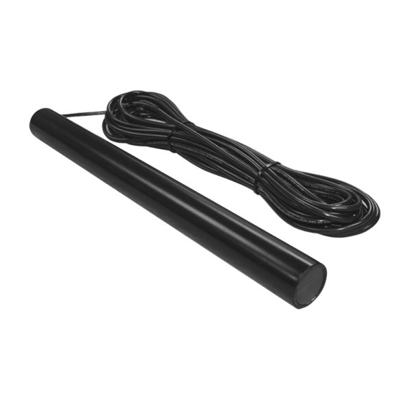
This is a magnetic REX (Request to EXit) sensor that’s buried near or under the driveway, and hard-wired to the gate controller. Driving over the sensor with a large, iron or steel object will cause the gate controller to automatically open the gate.
In our case, the sensor is about 15 feet from the gate.
So in summary, the keypad allows you to enter (if you know the code), the magnetic REX sensor allows you to leave (if you’re in a car), and the transmitter allows you to cycle the gate if you’re within about 20 feet of the receiver.
Shortcomings of the Existing System
This system has some serious shortcomings.
Transmitter has Limited Range
As mentioned, the transmitters have a range of about 20 feet, assuming a clear line of sight.
The transmitter has a clip, and normally sits on your visor, like a garage door opener.
When you approach the gate, this isn’t a problem, because you have a clear line of sight through the windshield of your vehicle.
If you drive through the gate and you want to close it behind you, you quickly find that your line of sight is now obstructed by your vehicle, which sometimes even entails holding the transmitter out of the car window to obtain a clear line of sight.
There’s a timer that eventually closes the gate automatically, but sometimes you want it to close immediately
In addition, there is no way that the transmitter will reach 300+ feet from the house to the gate.
Base Station is Useless
Although it’s supposed to allow you to open the gate from inside the house, the base station has a practical range that is much shorter than the distance from the gate to the house, which makes the base station useless.
I’ve read reviews on Amazon and other sites, that even when the base station works, reception and control are both spotty. They have an updated version, but it’s not worth nearly $300.
Can’t Remotely Program the Keypad
Although the keypad allows up to 25 codes, and even allows you to program temporary codes that expire after a certain number of days, you have to actually walk up to the keypad to program them.
There is no way to remotely administer the keypad (or, hey, tell it to OPEN THE GATE, either).
No Easy Way to Open from Inside
All of these small issues lead to a big one:
Aside from the REX sensor (which works VERY WELL, by the way), if you’re INSIDE the gate and you want to open it, there is no easy way to do this.
Here are your options:
- Drive up to the gate with a vehicle. Not practical if you’re just trying to go grab the mail, or let the delivery guy in.
- Walk up to the gate with a transmitter. It’s a long walk, and you might not be sure about who is at the gate. Especially in the rain, I’m going to be seriously disinclined to walk all the way out there to let someone in.
- Give someone the keypad code. This presupposes that you’ve programmed a series of temporary codes, or a throw-away code, and that you aren’t giving the delivery person one of your “main” codes. Also, although this allows you to let someone in, it won’t work if you are trying to get out (example: to check the mail).
- Lock the gate open. This entails walking up to the gate, opening it with a transmitter, and then using the toggle switch on the bottom of the control box to turn off the motherboard. Later, to close the gate, you have to walk back out to the control box and flip the switch again, and then either wait for the timer to close the gate, or use the transmitter to close it. This is a good option if you’re expecting a delivery, but not so good if you have to leave.
Can’t Tell Who is at the Gate
The other major problem is that you can’t easily tell who is at the gate.
Unless someone calls you and says “hey, I’m at your gate”, you have no way to know who is there and what they want.
Even if the intercom worked properly, from what I’ve read, the voice quality is poor, and you might not be sure who you are letting in.
Potential Solutions
With these limitations in mind, I started to think about possible solutions.
FM132 Push Button Control
The “Push Button Control” accessory is basically a doorbell button that is direct-wired in to the gate controller. When you push the button, it acts like one of the transmitters and causes the gate to cycle (open or close).
At first, this seemed like a good solution, but the exact distance limit isn’t clear, and I would probably have to bury or tunnel about 400 feet of cable in order to mount it in a convenient location.
The other issue, of course, is that the gate will probably time out and close before you could walk out there, so you’d still need a transmitter if you go out to check the mail.
WiFi Interface?
Since I actually get a decent WiFi signal everywhere on the property (including all the way out at the front gate), the second thing I did was to check to see if there is a WiFi interface available for the gate controller.
NO, THERE IS NO WIFI INTERFACE AVAILABLE FOR THE GATE CONTROLLER.
Build a WiFi Interface?
After looking at the list of accessories and their installation instructions, I started to think about building a WiFi interface.
My first approach was to sacrifice one of the keychain clicker transmitters, where I could simply bypass the pushbutton switch with a relay. This approach had some down sides:
- The transmitter runs off of a 12V camera battery, and would need to be mounted within about 20 feet of the gate controller in order to operate. This means that additional battery power would be required, and / or a larger battery would be required, in order to allow the transmitter and the WiFi interface to continue to operate for more than a few hours at a time without requiring new camera batteries.
- I would have to sacrifice one of my precious clickers, which aren’t cheap.
Fortunately, the gate controller board is very well documented.
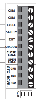
Each pin is labeled. The “Cycle” pin is how you would connect the push button control, allowing you to open or close the gate.
Looking at the “Safety” pin, the description seems to indicate that this would be a convenient way to remotely hold the gate open as well.
SAFETY: (Typically for use with photo beam device, loop detector or other non-contact sensors) • Activation of this input while the gate is closing will cause the gate to stop and return to the opened position. • Activation of this input while the gate is opening has no effect (gate will continue to open). • Activation of this input while gate is idle will prevent gate from closing.
So if I were to build my own interface, it would need to perform three functions:
- Cycle the gate by briefly connecting COM –> CYCLE. This would allow the user to open or close the gate.
- Hold the gate open by briefly connecting COM –> CYCLE, and then holding COM –> SAFETY. This would tell the controller to start opening the gate (CYCLE), and then hold it open (SAFETY).
- If the gate is being held open, release COM –> SAFETY, allowing the gate to close.
The more I thought about it, it seemed increasingly feasible that I could build an interface that runs off of the gate’s 12V DC battery, connects to WiFi, and allows the user to remotely perform the three functions listed above.
Solution Design
12V DC Power
The gate controller and the gate itself run off of a 12V DC battery located inside the control box.
The reason for this, is because you still need to be able to operate the gate during a power failure. I want my solution to run off of the same battery for the same reason.
Pi vs. Arduino
Raspberry Pi and Arduino are the two leading single-board solutions for hobbyist, embedded electronic applications.
Arduino is more of a programmable controller, where the Pi is a full-blown computer with programmable IO pins.
Both have an inexpensive, small-form-factor version.
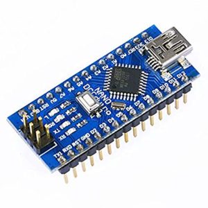
- Arduino Nano
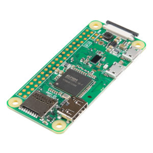
- Pi Zero
The Arduino operates at 5V through its USB interface, or, conveniently, 7 to 12V DC through the DC jack or its VIN (Voltage IN) pin.
The Pi ONLY operates at 5V through its USB interface, so going with the Pi means including a DC-DC converter. It also means using relays for the control pins on the gate controller, which operate at 12V and would fry the Pi.
The Arduino is basically meant to be a device, and that means no native WiFi support. Although there are addon boards for WiFi support, doing anything beyond a simple socket listener would probably require extensive coding, and a true server interface would be out of the question.
Conversely, the Pi Zero W includes on-board WiFi support, and the Pi is a full-blown computer, capable of supporting a more comprehensive range of server services, such as SSH and Apache.
So the choice was clear.
Although the Arduino has better support for 12VDC, WiFi integration would be much more complex.
Since the goal of this project is to take advantage of the WiFi coverage, the Pi made more sense, even though more hardware would be required in order to run from 12V and actuate the gate controller’s 12V input pins.
- On the Pi, I would easily be able to serve up a simple web interface, and perform remote administration via SSH.
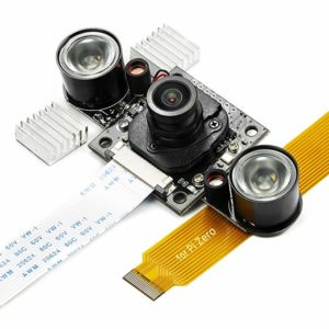
- As a bonus, the Pi Zero W has a camera interface, and integrating a camera in to the solution means that the user can also see who is at the gate before they open it – a valuable safety feature to have.
- The Pi boots and runs from a micro-SD card. Using a slightly beefier memory card would allow me to store video from the camera, just like a DVR system.
Integration with 12V DC
Having chosen the Pi as the base platform, two issues needed to be solved:
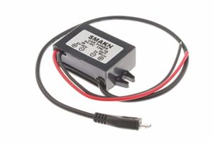
- Knowing that the solution must run from 12V DC, there must be a DC-DC converter that runs on 12V input, and provides 5V output, ideally from a micro USB connector (phone charger connector) that the Pi uses as its input power.
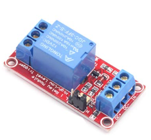
- Knowing that the gate controller’s input pins operate on 12V, but the Pi’s GPIO pins operate at 5V, there must be a 5V relay for each of the two pins I intended to control (CYCLE, SAFETY).
Fortunately, it was fairly easy to find both a 12V-5V DC converter, as well as 5V, optically-coupled relays that are designed to drive AC or DC voltages up to 240V – well beyond anything I’ll be using.
Software
A simple web interface would allow anyone on the property to view the camera or operate the gate from a phone or laptop.
Apache + PHP made the most sense for the UI.
For the back end, rather than have a mashup of PHP shelling out to call Python, I opted for WiringPi, which is already built in to Raspbian, and provides the gpio command-line tool. PHP calls a handful of shell scripts, which then use the gpio command to operate the gpio pins.
To drive the camera, I opted for Motion, which is a simple event-driven webcam interface and controller.
I was also able to write a simple media server using PHP, so that you can view videos and stills recorded by Motion.
Here is the main user interface:
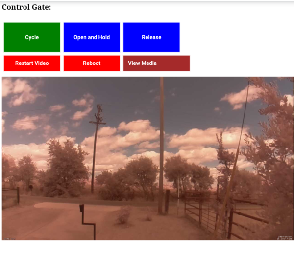
- Live feed from the camera
- The green button opens / closes the gate using the CYCLE pin.
- The “Hold” button opens the gate using the CYCLE pin, and then and holds it open (using the SAFETY pin), while the “Release” button cuts off the SAFETY pin, releasing the gate.
Media Server:
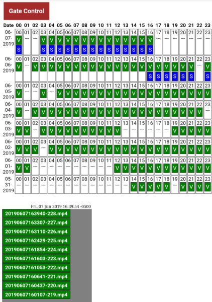
- A list of dates is listed on the left, and the hour of the day is listed across the top.
- A “V” tells the user that there are one or more video files for that date / time, while “S” indicates still frames.
- Clicking a “V” or “S” in the grid above lists files for that date / time below.
- Clicking on a specific file opens it in a new browser tab:

Putting it All Together
I mounted the camera on top of a 6ft pole next to the gate.
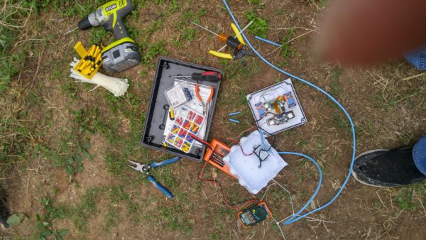
Here is my messy work area:
Here is a close-up of the finished product:
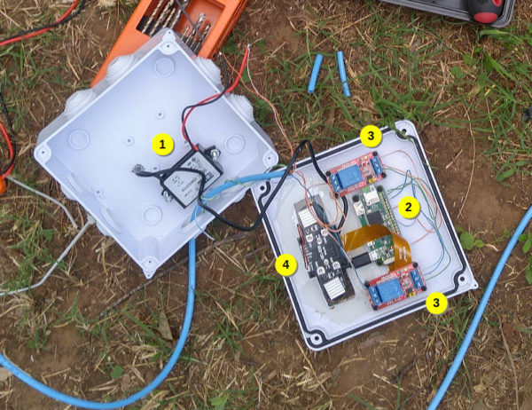
- DC-DC 12V to 5V converter. Note the micro-USB plug connected to the Pi’s power interface. This converter worked really well over a range of voltages. On my test bench, I had it connected to a PC power supply that was putting out about 11.6V, and voltage at the battery terminals in the gate control box ranged from 12V to 13.6V (voltage drops a bit when the gate is being opened or closed). The 12V terminals are hard-soldered, and I used the two little snippets of blue jacketing (top-middle) to cover the two solder points.
- Pi Zero W. Rather than using the header, I hard-soldered wires to the pins I needed.
- Each of two 5V relays. These are optically-coupled, and run directly from the Pi’s Vcc, 5V, and GPIO pins (connected on the right). The gate controller’s pins connect on the left.
- Day / Night camera. You’re seeing the back of the camera. Those two heat sinks are attached to each of the LED infrared flood lights. I cut a rectangle in the enclosure, then used epoxy to insert a clear plastic cover, so that the enclosure remains completely waterproof.
Here is a shot of the gate controller box:
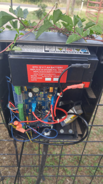
- I had to replace the battery connectors, which were worn and rusted.
- This shot was taken before I connected the 12V power supply directly to the battery connectors.
- Rather than use a separate com for each of the control pins, I shared one com connection and bridged it internal to my WiFi interface. This shot was taken before the three pins (COM, CYCLE, SAFETY) were connected on the lower-left.
Additional Pictures and To-Do
[Added: 2019-06-12]
Additional Pictures

- I drilled a small hole through the bottom of the controller box for the CAT5 solid-core cable that I used for my bus cable. The brown / brown-white pair are 12V power, soldered to the buck converter on the other end. This picture was taken after I installed new battery terminals.
- Orange-white is com(mon). Blue is connected to the CYCLE pin. Internal to the wifi interface, orange-white is bridged to the com pin of the cycle relay. Orange is connected to the SAFETY pin.
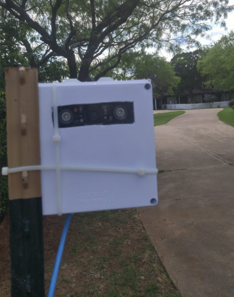
The wifi interface in its IP65 enclosure.
I used a piece of CAT5 solid-core as a bus cable.
The two infrared illuminators (left and right) are visible next to the camera (center)
To-Do List
- I had a failure condition, where the linux kernel apparently continued to function, but the wifi interface disconnected and failed to reconnect. Because the power is hard-wired to the gate controller’s battery, a simple reboot required partial disassembly of the gate controller in order to disconnect the power for the wifi interface.
- [DONE] A simple script will ping the gateway once per hour and reboot if no reply is received.
- [DONE] A Normally-Closed (NC) pushbutton switch will be installed behind one of the rubber grommets, allowing a manual reset without disassembly. Pushing the switch will interrupt the normally-closed positive lead to the battery, triggering a power-off and reboot once the switch is released.
- [Update, 8/3/2022] The ping script works well. Occasionally, I have to reset the RPi using the pin switch, but not very often.
- The IR illuminators bounce off the acrylic lens, making true night vision impossible. I will install a baffle around the camera lens, blocking out the reflection from the IR illuminators.
- [Update, 8/3/2022] I ended up removing the IR illuminators and installed a better light.
- This project worked so well as a wifi camera, that I plan to add several more throughout the property.
- Currently, the housing is zip-tied to the T-post, but I intend to install proper brackets, allowing the camera angle to be adjusted.
- [Update, 8/3/2022] STILL zip tied to a T-post. The zip ties broke about a year ago. I replaced the zip ties. :-)
Master Cable Break-Out
[Added, 8/3/2022]
After some extensive troubleshooting, I’ve determined that the gate opener’s motherboard died. :-/ Stay tuned for more info about its replacement ($350, by the way) [Update: 8/7/2022] The control board was in fact, dead. See below for more details.
However, during the process of troubleshooting, I learned WAY MORE about the Master cable than I cared to, but I thought I would share. Several people asked me if I had a solution for detecting if the gate is open or closed or cycled, and this may lead the way to a solution.
The “Master” cable is the umbilical cord that connects the motherboard to the arm, and is connected to one of the motherboard’s terminal blocks. If you have a DUAL-opening gate opener, then you also have a “slave” terminal block on the motherboard next to the “master”, and the wires should be the same between the two. Mine is a single-opener…
Inside the arm is a gear motor and a sensor board with two sensors:
- Limit switch: Trips when the arm fully retracts. This tells the motherboard that the arm is fully-retracted.
- Rotary encoder: Spins with the gear motor. An optocoupler senses regularly-spaced holes in a plastic disc, and pulses when the optocoupler is obstructed. The motherboard presumably counts the pulses in order to figure out the arm’s position.
I should have gotten a picture of it, but… life happens.
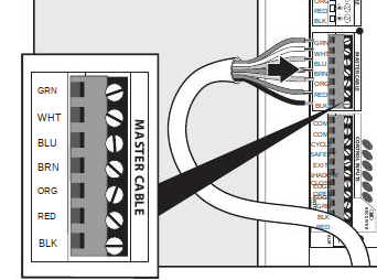
| Color | Purpose | Signal |
| GRN (Green) | Sensor Common | Ground for rotary encoder and limit switch |
| WHT (White) | Rotary encoder | Pulses almost +12V when motor is spinning. Unfortunately, you can’t tell direction JUST from the encoder.
Note: This pin will STAY at +12V as long as the optocoupler is blocked. |
| BLU (Blue) | Enables +12V for rotary encoder | (Not sure – I suspect that this is just VCC for the optocoupler’s transistor) |
| BRN (Brown) | Limit switch – Normally-Closed (NC) | +12V when the arm is NOT fully retracted
0V when the arm IS fully retracted |
| ORG (Orange) | Limit switch – Normally-Open (NO) | (Opposite of BRN)
0V when the arm is NOT fully retracted +12V when the arm IS fully retracted (I might have NO and NC reversed – I did so much troubleshooting that I honestly don’t remember for sure) |
| RED (Red) | Motor DC | Red and Black directly drive the 12V DC motor, and reverse polarity to reverse direction.
When closing, +12V When opening, GND |
| BLK (Black) | Motor DC | When opening, +12V
When closing, GND (Opposite of RED) |
Using one or some of these signals in conjunction offers some possibilities for monitoring the gate’s position, presumably using the same method that the motherboard uses.
Use an optocoupler isolation board to convert 12V signals in to 3.3V or 5V – there are multi-channel boards available in a wide variety of input and output voltages.
- The motor wires can tell you WHEN the gate is moving, and WHICH direction. With careful monitoring, you can tell HOW LONG the motor ran in each direction, and with some in-software guestimation, you could theoretically know the gate’s approximate position at any time. Be careful to ensure that any monitoring circuitry is VERY low resistance, or you run the risk of over-taxing the motor.
- The optocoupler can tell you THAT the gate is moving, but not in which direction. Counting pulses would allow you to figure out roughly how far it traveled.
- The limit switch tells you if the arm is FULLY retracted or NOT fully retracted. This comes with a couple of caveats.
- One nice feature of the limit switch is that you can get a high signal for either condition.
- However, if your opener’s arm doesn’t fully retract, it will never hit the limit switch. So if you have the open limit set to anything except fully retracted, the switch will never trip. I don’t know what openers support which features, but mine depends on the limit switch, and can’t be configured.
- If the gate STARTS to close, but stops for some reason, or if the hinge breaks, your gate won’t be closed, but you would never get a signal from the NO pin, because the arm isn’t retracted, and you WOULD get a signal from the NC pin, despite the fact that the gate isn’t really closed.
I don’t know how the stall sensor works, but I assume it either measures amperage through the motor, or looks at the optocoupler to slow down if the gate is “pushing” (or “pulling”) against an obstacle. In either case, I don’t think this would be reliable as a “sensor”.
So, hopefully that helps. If I end up adding some monitoring to the master cable, I will update this post subsequently.
Replacement: Mighty Mule MM571W
[Added, 8/7/2022]
On Wednesday, 8/3, the control box started making erratic beeping sounds, and the arm would no longer operate.
Troubleshooting – MM560
In case this benefits someone else, I’ll include the troubleshooting that I performed on the MM560 control board, which by the way is a R4211 (not sure which rev) single-operator (single-arm) control board.
Arm Disassembly Procedure
The arm is called an “operator”, but I’ll refer to it as an “arm”.
There is a fixed side, that I’ll refer to as the “shoulder” (not an official term)
There is a moving side, that I’ll call the “wrist” (not an official term)
The moving part of the arm slides in and out of a plastic cover, which comes apart in 3 pieces: A collar, an upper cover, and a lower cover.
- Turn off power to the control board
- If you can remove the arm from the gate and post, do so. Otherwise, you’ll probably have to crawl around on the ground in order to remove the Torx screws.
- If the arm is retracted, you have to manually extend it slightly in order to get the collar off. Holding the moving part of the arm, and looking down the arm past the wrist and toward the shoulder, unscrew the moving part of the arm (counter-clockwise) by about 10 turns. This should lengthen it slightly.
- Unscrew the collar (counter-clockwise) until it comes free from the rest of the cover.
- Use a Torx T-25 to remove the 14 screws from the bottom of the arm.
- At this point, the lower and upper cover should separate from the arm.
- The upper cover can be completely removed and set aside for reassembly later. PAY CAREFUL ATTENTION to the cable routing so that you can duplicate it when reassembling.
- The lower cover is where the cable enters, and where the sensor board is mounted. The motor is mounted to the piston assembly, and (on mine at least) connected to the master cable by two wire nuts.
- If needed, you can now remove the sensor board by disconnecting the 5-pin connector to the master cable, and removing a single Torx T-25 screw.
To reassemble, follow the steps in reverse. BE CAREFUL to route the cables identical to how you found them. Also, be sure to reconnect the jumper on the master cable to the sensor board.
Troubleshooting Procedure
- Beeps and Blinks. There is a troubleshooting guide at the back of the installation manual. In my case, I was either getting 3 beeps or 5 flashes (accompanied by 5 beeps), and this seemed to happen randomly. 3 beeps indicates a problem with the motor – either a cable issue or a short across the motor. 5 flashes (in my case, accompanied by beeps) indicates a sensor issue.
- To troubleshoot the sensor issue, I removed the wires for the magnetic wand from the terminal block, and also the wires for my custom gate controller. No luck.
- To troubleshoot the arm, I disassembled it. In retrospect, I could have done all of this troubleshooting from the control board, and disassembly was NOT required, but hey, I didn’t know that at the time. So, to be clear, you can perform ALL OF THESE STEPS WITHOUT disassembling the arm.
- Test the limit switch. Make sure the arm is FULLY-RETRACTED, and turn the control board OFF. You can retract it by hand if needed – turn OFF the control board, disconnect the wrist, then screw the piston clockwise until it reaches the fully-retracted position.
- Check continuity across GRN and ORG (I might confuse BRN and ORG – check both), and you should get a tone or 0 Ohms. You should get E or infinite (no connectivity) across GRN and BRN
- Unscrew the wrist a few turns, and check again. Whatever you got before, you should get the opposite now. For example, GRN-ORG should be E or infinite, and you should get a tone or 0 Ohms on GRN-BRN.
- With the control box ON, and the arm in ANY position, check voltage and you should get 12V across either GRN-ORG or GRN-BRN.
- Test the rotary-encoder. With the Control box ON:
- Check voltage across GRN-BLU, and you should get like 3 or 4 volts – BLU I think is Vcc for the encoder, and it seems like it’s normally tied low. In my case, this was difficult to test because the control box kept rebooting, but just be persistent.
- Voltage across GRN-WHT should be 0V or near 12V (like 11.6V). With the optocoupler clear (not obstructed), you should get near 12V. If the optocoupler is obstructed, you should get 0V. Give the arm a turn – maybe 30 degrees and make sure it changes. In my case, I used a small piece of paper to block the optocoupler.
- Test the motor. With the control board OFF:
- Unscrew the RED and BLK wires from their terminals, and connect the wires straight to the battery (red-to-red, black-to-black) and the arm should extend. Use jumper wires if needed.
- On the master cable (not the terminal) connect RED and BLK to the battery, opposite terminals (red-to-black, black-to-red) and the arm should retract.
- With RED and BLK wires, put your meter in 30 Amp mode (move the probe to the 30 Amp terminal). Connect the BLK wire to the battery’s black terminal. Connect the RED wire to the black probe on your multimeter. When you touch the red probe on your multimeter to the red battery terminal, the motor should spin. Don’t leave it there more than a second, or you could melt your probe wires! However, you should read (according to Mighty Mule) no more than 2 Amps. In my case, the motor was free-wheeling because the arm was disassembled, and I was reading 0.25 Amps (no load on the motor).

No luck. At this point, I highly-suspected a dead control board.
Mighty Mule Support
Let me start off by saying that Mighty Mule has the best tech support of any company that I’ve dealt with in the last 20 years. The person who helped me was knowledgeable about the products (multiple models), understood the problem, understood the troubleshooting that I had performed, and made helpful suggestions about next steps. Also, instead of just trying to sell me new parts, he took the time to work with me, to make sure I had thought of all of the options. So, A+ for Mighty Mule support.
Knowing that worst-case scenario, I was going to have to shell out $350 for a new R4211 board, I decided to call tech support, just to see if there was anything I missed, and see if they agree with my diagnosis.
Fortunately, support was excellent.
UNfortunately, it was a dead control board, and the MM560 is now far past end of life.
So the technician made the suggestion that, instead of shelling out $350 for a control board, why not go buy a new TS571W for only about $100 more? He asked me about the weight and length of the gate to make sure of which opener I needed, and then suggested the one from Tractor Supply – it’s packaged as TS571W but it’s the same as a MM571W, and it’s only $470.
This made good sense – not only was I getting an entirely brand-new unit, but the entire thing would be under manufacturer warranty, not just the control board.
Caveats About the TS571W vs MM571W
The TS571W Tractor Supply version is functionally identical to the Mighty Mule MM571W version, but it’s about $50 less expensive.
Here is why it’s less expensive: It doesn’t come with a battery nor a battery box. Both of these are pretty important, since the arm and the control board run off the battery.
I don’t think the Mighty Mule technician knew that it doesn’t come with the battery box.

On the left, the Tractor Supply version is $470. It comes with the control box, the arm, two remotes, and some mounting hardware.
On the right, the one from Lowes is the Mighty Mule version, and comes WITH the battery and battery box, which mounts behind the control box. In the center one, you can see that the control box (really two boxes) is deep enough to hold the battery, as opposed to the one on the left which is only about 3 inches deep because the battery box isn’t included.
In the instructions for the MM560, you can see that it comes with the “control box” which also holds the battery:
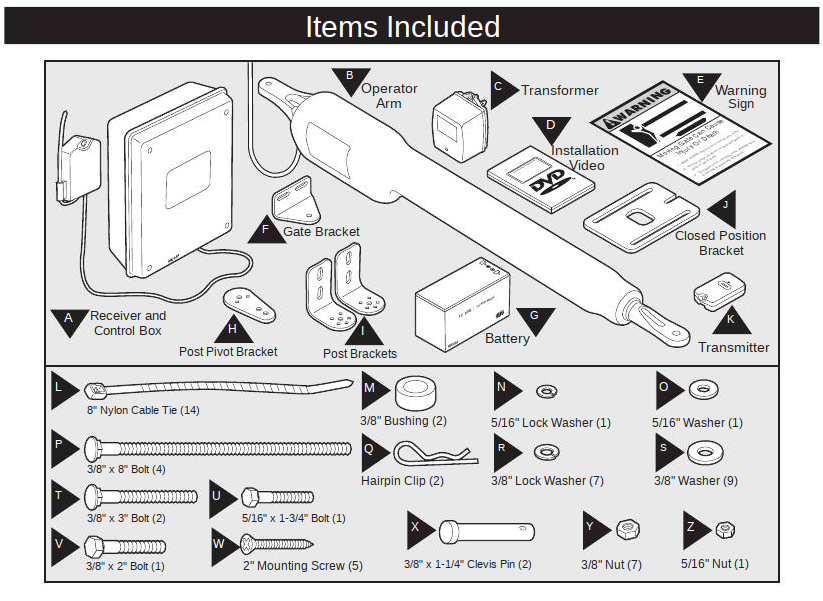
Items Included – MM560 (Obsolete)
In the instructions for the MM571, you can see that it also comes with a battery and the battery case:
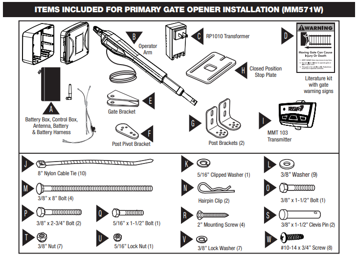
Items Included, MM571W (Mighty Mule)
The Tractor Supply version’s instructions make no mention of the battery except for the jumper harness which connects it to the control board:
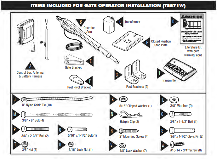
Items Included – TS571W (Tractor Supply)
In fact, it makes almost no mention of the battery at all – I had read the MM571 instructions online before my wife even bought the new unit (I’m a nerd, remember), so my first reaction when I opened the box was “Wait… there is something missing”. I had to re-read the TS571W instructions multiple times. The next and LAST time the battery gets a mention is 8 pages later:
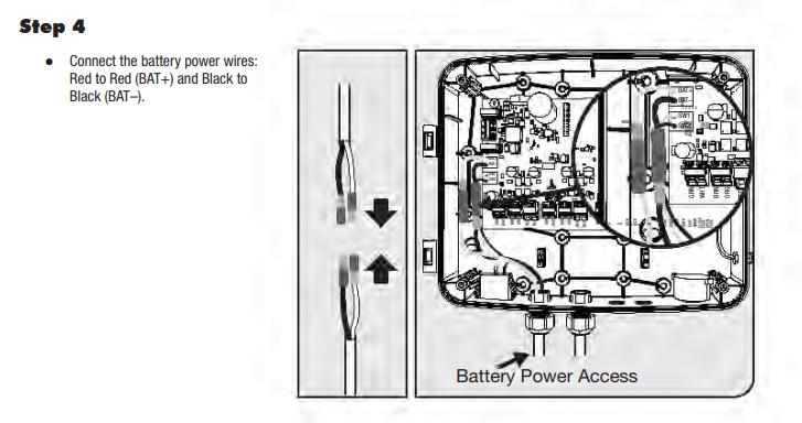
TS571W Instructions (Tractor Supply)
Connect the battery. Uh…. FROM WHERE? So apparently, you’re supposed to “just know” that you need an external battery box and battery.
In contrast, here is the same page from the MM571 instructions:
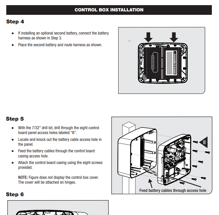
MM571W Instructions – Mighty Mule
So the battery was no problem, because I already had one from the old unit.
But where am I going to find a battery box on a Saturday? Even Tractor Supply doesn’t sell one of the proper size. I could go to the hardware store and try to rig something together using an outdoor electrical box, but what a hassle.
After thinking about it for a few minutes, I compared the mounting holes for the R4211 board (old, 560) to those of the 571, and guess what? They have the same mounting holes.
So I took the new 571 control board out of its brand-new case, and installed it in my old, crappy 560 box. Take THAT, Tractor Supply.
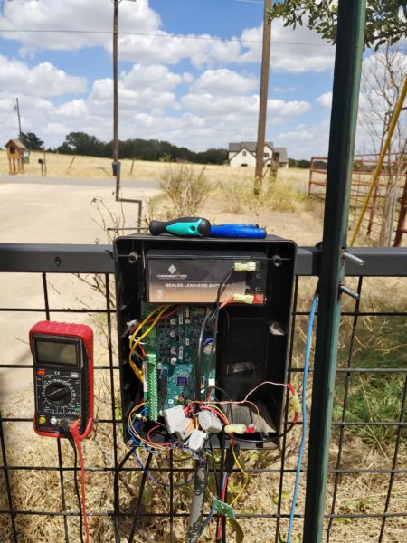
Here is the NEW 571 board installed in the OLD 560 box, WITH battery :-)
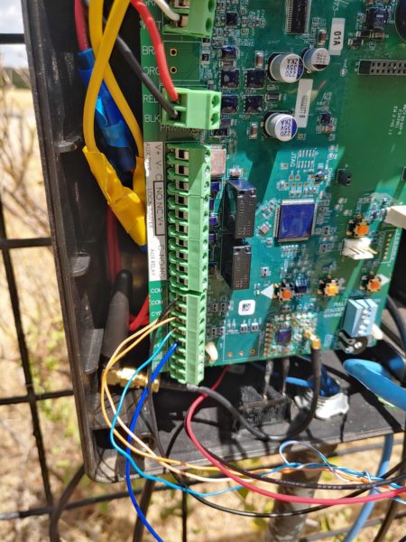
Here is a close-up of the terminal, with everything connected. I had my wires from the RPi confused – brown-white is common, brown is cycle, blue is safety (hold), but I figured it out after some troubleshooting. The red and black wires (top-center) go to the master cable – these are the motor’s power wires.

Here is a close-up of the power terminal (top), and the sensor terminal for the master cable. Instead of 5 sensor wires, the new model only uses 2! I measured across GRN-WHT which measured about 2.6V with the gate closed. I’m assuming thatt this is connected to a linear resistor of some kind – I might take some additional measurements later.
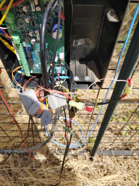
I built a “power bus” using 5-position lever nuts. These things are great! It looks a little messy, but Mighty Mule insists that splicing their battery harness will void the warranty, so I added pig-tails to connect the battery, more pig tails to connect my RPi, and was even able to connect the power terminals for the magnetic REX sensor.
Unfortunately, the cable for the magnetic sensor is a PITA to deal with. It has a braided metal shielding and about the toughest jacket I’ve ever seen on a cable. So rather than fight with this thing and strip the several inches necessary to connect everything, I jumpered the two terminal connections and the potentiometer (adjusts the sensitivity) using more lever nuts.
Lever nuts are the greatest thing since sliced bread.
Meanwhile, I think I used every tool from my office and half the stuff in the garage. I used my wife’s truck as a work bench, and every time I said, “I need to go grab something from my office”, her look became increasingly consternated. In addition to simply installing the new control box and arm, we ended up having to make several minor repairs to the fence, necessitating even more tools and stuff. She is a saint for putting up with me.

And yes, a beer is well-deserved after spending all day in the heat installing this thing.
A Couple More Caveats – Nothing Major
I checked both manuals (TS571W and MM571W) and the instructions for setting the extended limit are INCORRECT.
- Press and hold ↵ and ↑ (Enter and Up) simultaneously until it beeps.
- Use ↑ and ↓ (Up and Down) to move the gate more closed or more open respectively.
- The instructions say “Press ↵ to set the limit”. This is INCORRECT. Instead PRESS AND HOLD ↵ until it beeps.
We spent 30 minutes trying to figure out why the stupid thing wouldn’t open.
Also, the newer style (3 button) transmitters are crap. Each one has three function buttons, and each button acts like a separate transmitter, so you can actually program any or all of the buttons on each transmitter using the motherboard’s “learn” function (Press and hold enter until it beeps, press the transmitter button until it beeps). However, the range is crap – probably half the range of the old transmitters. Mighty Mule sells other accessories, such as garage door openers that interoperate with the same transmitters, so that in theory you only need one transmitter. The “A” button might open the gate, while the “B” button opens the garage, and maybe you have another gate at the back of the property, which can be operated with the “C” button. Good idea, poor execution. Unlike the old transmitters, you can’t set the codes – they are fixed at the time of manufacture, and each code is unique, but that’s not really an issue. The lack of range, however, is a huge issue.
Fortunately, the old transmitters interoperate with the new system, which is a great design! The old transmitters have a digital code that you set via DIP switch inside the transmitter. On the 560, you would set ALL of your transmitters to the same code, then learn that code on the controller. On the 571, all you have to do is learn one of your 560’s transmitters, and assuming they are all set to the same code, they are all now remembered by the controller. However, the 571’s controller can store up to 50 codes, so in theory you could set each one to a different code, or have two different groups, etc.
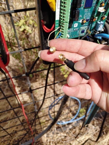
The dinky antenna has a very short range. To use the new transmitter with the dinky antenna, you have to be practically standing on top of the control box. Not good. The 560 had an external receiver so that you could mount the antenna high enough to get a decent range. The 571’s receiver is incorporated in to the controller board, and the cable is maybe 6″ long. In the original 571 control box, the antenna screws on to the side of the box. I’m hoping that adding a 2 foot extension cable will help significantly.
Summary
For about $50, 200 lines of code, and about 2 weeks of development, I built a WiFi interface for my Mighty Mule gate control system.
- View a live feed or operate the gate using WiFi, anywhere on the property from a smart phone or laptop
- Automatically records motion “events” locally, that are continuously downloaded to a Linux PC inside the house
If anyone is interested, please reach out to me, and I’m happy to share parts lists / scripts / code / config.
Pingback: Gatetrilogy Saga: The Front Gate Part III, The Final Gate Opener | Justin A. Parr - Technologist
Pingback: Rant: SMA vs. RP-SMA | Justin A. Parr - Technologist
Pingback: Gate Opener Replacement | Justin A. Parr - Technologist
Pingback: C – Access Other Data Types As Byte Array | Justin A. Parr - Technologist
Hi Justin, I am trying to do something similar to this but having some issues writing the code. I was hoping you would share scripts / code / config. Thank-you and best regards
Hi, JustMe:
https://justinparrtech.com/JustinParr-Tech/wp-content/uploads/gatecontroller_pi_20200513.zip
I included some high-level instructions. Let me know if you get stuck.
I put this in almost 3 years ago, and it still works very well.
I already have a pi serial, it’s just been too cold to sit out at the gate with a multi-meter and laptop. Besides just curiosity, the serial is my last resort. My uController is a Sparkfun XBee Thing. Processing the serial output would be more complicated there, I think.
Some other control board connections I’ve thought of using are the gate lock or warning light, either should have current while the gate is in motion. I don’t have a warning light connected and the lock is useless when the gate is mounted on a wooden post. The lock and latch pin is perpetually out of alignment due to the weather affecting the post. I don’t believe these help with which direction it’s moving.
I have a sort of similar setup. my Raspberry Pi is currently in my garage and remotely operates the gate via the cycle pins. I have a wi-fi web cam on my gate opener page that shows me if the gate is open or closed.
Have you found anything on the mighty mule gate opener motherboard to let you sense if the gate is open or closed? That’s my next step. I want to be able to send it a command like open and not have it close if it is currently opened. I don’t want to rely on the web cam image.
I just got a pi zero wh and am going to try and mount that in my control box and see if I can get wi-fi to my house and then try and figure out the best way to programmatically figure out if the gate is open or closed.
– jack – Southlake Texas – https://mylinuxguy.net
Hi, Jack:
I had the same thought about sensing the gate position (or state). I haven’t found anything yet. There is nothing obvious on the mobo nor the documentation for the mobo that says “hey connect here to sense the status”, but I suspect that there must be a way to do it. I also thought about a simple NC switch on the gate arm that is depressed (open) when the gate is closed and closes when the gate is opened.
Please let me know if you want my (messy) PHP source code – happy to share. If I find any way to sense the gate position, I’m happy to share, and would appreciate same.
-JP
Also interested in gate direction. Surely the solution lies in the color-coded swing-arm wires. It should be possible to detect a change in polarity, or voltage present on a given wire, rather than resorting to external sensor devices. Any progress here?
Hi, Don:
In short, not yet!
No progress about detecting the state of the gate internally (yet). I agree that some time with a multimeter might yield something useful, and then because of the voltage difference, I would need an ADC module or a similar circuit that senses the “drive” signal and reduces it to +/-5 volts that I can detect on one of the Pi pins. Although this would tell me if the gate is opening or closing it wouldn’t tell me the absolute state – for example, if the gate started to close, but hit something and stopped. What I was hoping for is a way to tap the board’s state, since it knows whether the gate is open or closed (or somewhere in between), but there are no pins for this.
Reading your comment, I hadn’t considered that perhaps the actuator itself might have a position sensor, so I’ll have to check that out. If so, then you could theoretically read the position in real-time, assuming you know how to decode the sensor pin. I had always just assumed that it uses PWM to calculate the gate’s position, which I assumed is why it’s so sloppy. X pulses = 1 spin. Y spins = 1 cm. z centimeters of travel = x * y * z pulses. What further makes me think this, is that if you kill power to the gate half-way through its cycle, it ALWAYS opens – the circuit is probably looking for a current spike which indicates that the gate is fully-opened. Then, the controller just blindly sends pulses.
The other approaches I’ve been considering are:
– Magnetic switches – the gate is too imprecise
– Potentiometer / Optical encoder connected to the gate hinge – would get banged around and knocked out of alignment over time
– Linear potentiometer / Linear encoder connected to the actuator (TBD)
– Some kind of mechanical deflection sensor (TBD)
– Optical sensor (trip beam) – would be running (and draining power) continuously. If I run it from the battery, it will drain power from the battery. If I run it off of a separate circuit, then it won’t work during a power outage.
No progress yet, though.
It has a magnetic sensor and a wheel in the swing-arm assembly, and a PCB that counts the revolutions. The other thing I’ve considered is tapping the “debug” serial port to see if it offers any useful state information. I’ll be running zigbee motes off the battery with a solar charger, but I’d like to avoid drawing more power than necessary as well.
I’m mainly a professional software guy, my circuitry reverse-engineering foo is weak.
Good to know how that works. I wonder if I could add my own reed switch to the encoder you describe – that would at least tell me the gate is moving, although not necessarily in which direction. I guess I could add two reed switches, and use the A->B vs B->A logic…
Also, I didn’t realize there was a serial port… very cool! Assuming they use 4 pins, one should be +5 or +3.3 and one should be -5 or -3.3. The other two are TX and RX, which you should be able to plug in to either a USB serial adapter, or use the Pi’s serial interface.
So, I finally had the occasion to figure out the signals on the master cable – See updates in the main post. There might be some useful options, and please let me know if you’ve come up with anything in the interim. Hope this helps…
Pingback: HOME | Justin A. Parr - Technologist